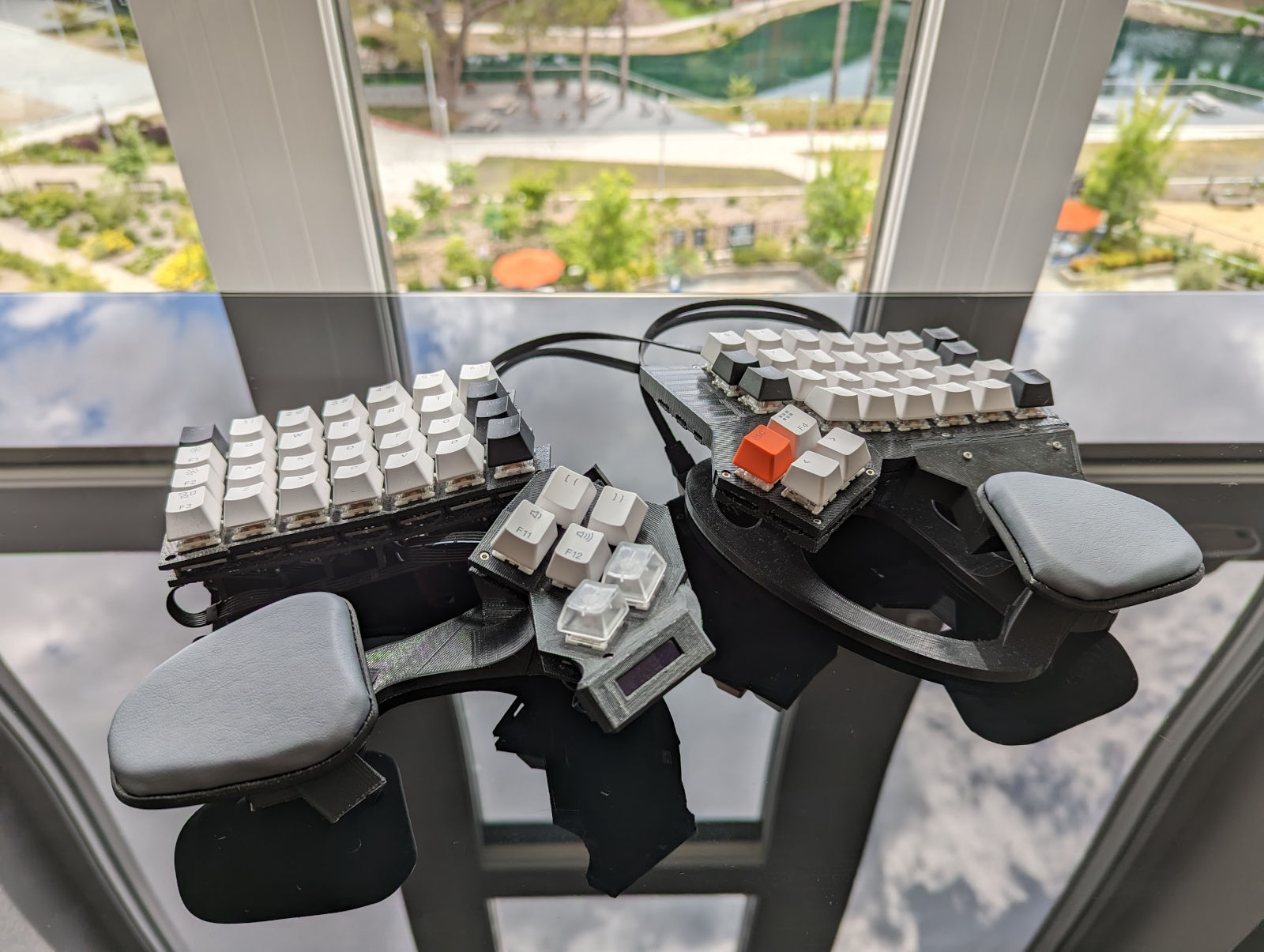
In my last post I presented my quest for a suitable MS Natural 4K replacement. After exploring some options I casually declared I was going to build one from scratch. Well, 230 hours later I actually did it. I’m even typing this post with it now! Today, I rather proudly present “DerBard”. Allow me to share the story of how it came to be.
OK, at first glance it looks nothing like the MS Natural 4K but it’s ergonomically very similar. The primary goal is for it to be similarly comfortable for long term use.
- The overall shape and curves are actually based on physical scans of the 4K
- Slight backwards tilt to keep the wrists straight
- Custom palm rests in the same positions as the 4K
- Thumb clusters to avoid 5th finger strain from holding Ctrl
I’d like to showcase the work and decisions that went into making it, my excitement through the process and satisfaction with having finished the project. Maybe it helps someone else out there doing something similar.
Table of contents
- DerBard Summary
- Custom Keyboard Background
- Design and Modelling
- Mounting the switches
- Shape
- Adjustability
- Assembly
- Software
DerBard Summary
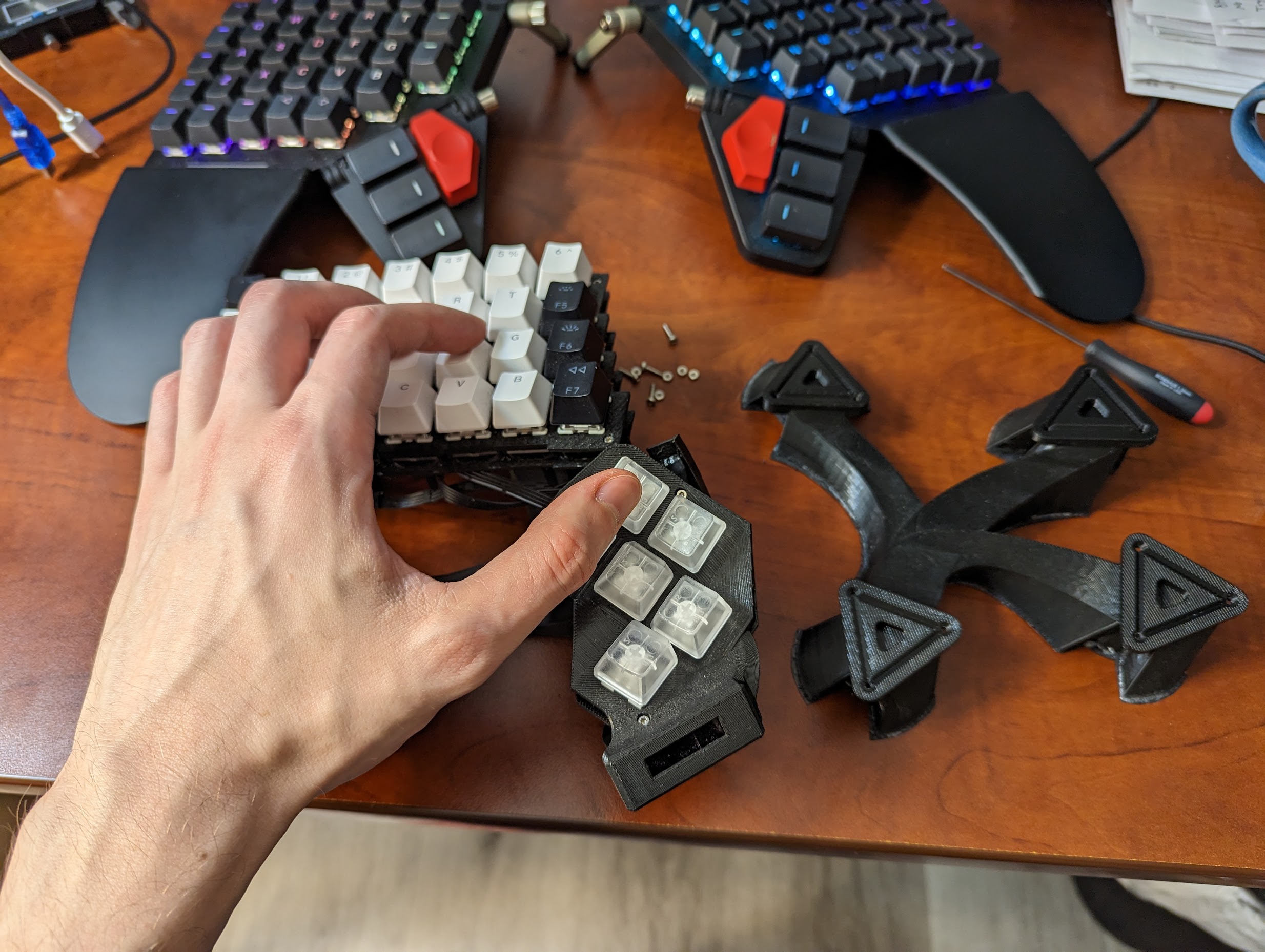
It’s an ergonomic split 65 key keyboard with inbuilt palmrests, backwards tilt and per-key RGB lighting. It’s a dream for typing text. Probably because it was designed to match the raised MS Natural 4K that I already love. The left thumb cluster is plain bad and needs redesigning — the redesign is on the right.
It’s fully programmable with an Arduino ATmega32u4 (Elite-C V4 board), runs QMK, has a 128x32 pixel display, buzzer and animated indicator LEDs that I use to show what layer is active. I’m recycling switches and keycaps from an off-the-shelf keyboard with some clickeys for the modifiers on the thumb clusters.
The project was a considerable endeavour, totalling 230 hours of design and construction. I started with a fully functional left half, which took 150 hours. The right took another 80 hours, including revised approaches to the design and manufacturing steps. Stretching from July 2022 to April 2023, this project spanned nearly 6 full time working weeks. The majority of the time by far was design in Fusion360. Printing, assembling and programming was relatively quick - just a few weekends. Throughout the journey, I encountered numerous challenges, made mistakes, and gained invaluable insights.
A few things set this apart from other designs I’ve seen:
-
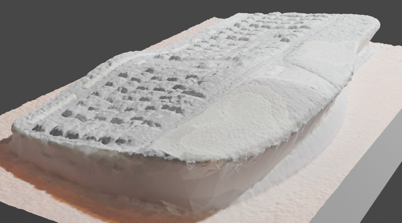
I attempted to match the shape of the MS Natural 4K by scanning it.
 3. The board is not flat and I used 1x1 PCBs mounted in a 3D printed plate to do it. This key holder design is my own.
4. The right hand half uses a GPIO expander instead of a second microcontroller. 5. Per-key RGB. Not practical, but it was fun.
Custom Keyboard Background
This is my quick summary and background of custom mechanical keyboards before talking keyboard details. It was so quick I had to split it out to a separate page:
Design and Modelling
These were my broad stroke starting points: - How do I mount the keys? - What shape will the keyboard have? - What if I get it wrong, can it be adjustable? - Thumb clusters look interesting, do I want one?
Mounting the switches
By now I’d been browsing r/MechanicalKeyboards/ for some time and could see I had some options. It seemed like most people were buying PCBs and plates from keeb.io. PCBs didn’t work for me as the whole point of this project was not to make a non-flat MS Natural 4K replacement. Actually there is one caveat here — keycaps come in different heights (e.g. you’ll find function keys at the top are often taller) and a coleague at work showed me you can get a good curve even by gluing on some Lego shims.
I was rather inspired by Dactyl in how a whole board could be 3D printed minus wiring the switches to a microcontroller. I highly recommend the talk. Many people don’t even bother with a flexible PCB and solder diodes and wires directly to the switches. One rather eye-catching project was a Dactyl Manuform with hot-swappable sockets. This is where I thought I’d start.
I recently bought a CR-10 printer and started learning Fusion360. My plan was to design a keyboard just like dactyl in that the shape could be quite organic. The starting point for designing a switch mount was this video by Bastard Keyboards. The reminder to print test pieces along the way is a great tip!
RGB lighting is just a gimmick and doesn’t really make you type faster. I’m kidding, of course my eyes got the better of me. I’ll have some of that! I eventually stumbled upon 1x1 NeoKey PCBs.
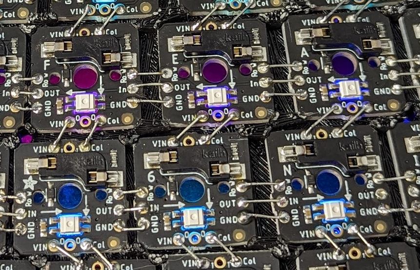
Pre-assembled socket + diode + RGB LED PCBs with convenient connections to adjacent ones. Not super cheap mind you, but convenient enough for what I’m getting. I found you can buy them in 5x5 snap-apart grids. Three sets for $90 + postage and that’s just the start. Fair warning: you don’t want to run the LEDs at full power unless you have a 20% size keyboard.
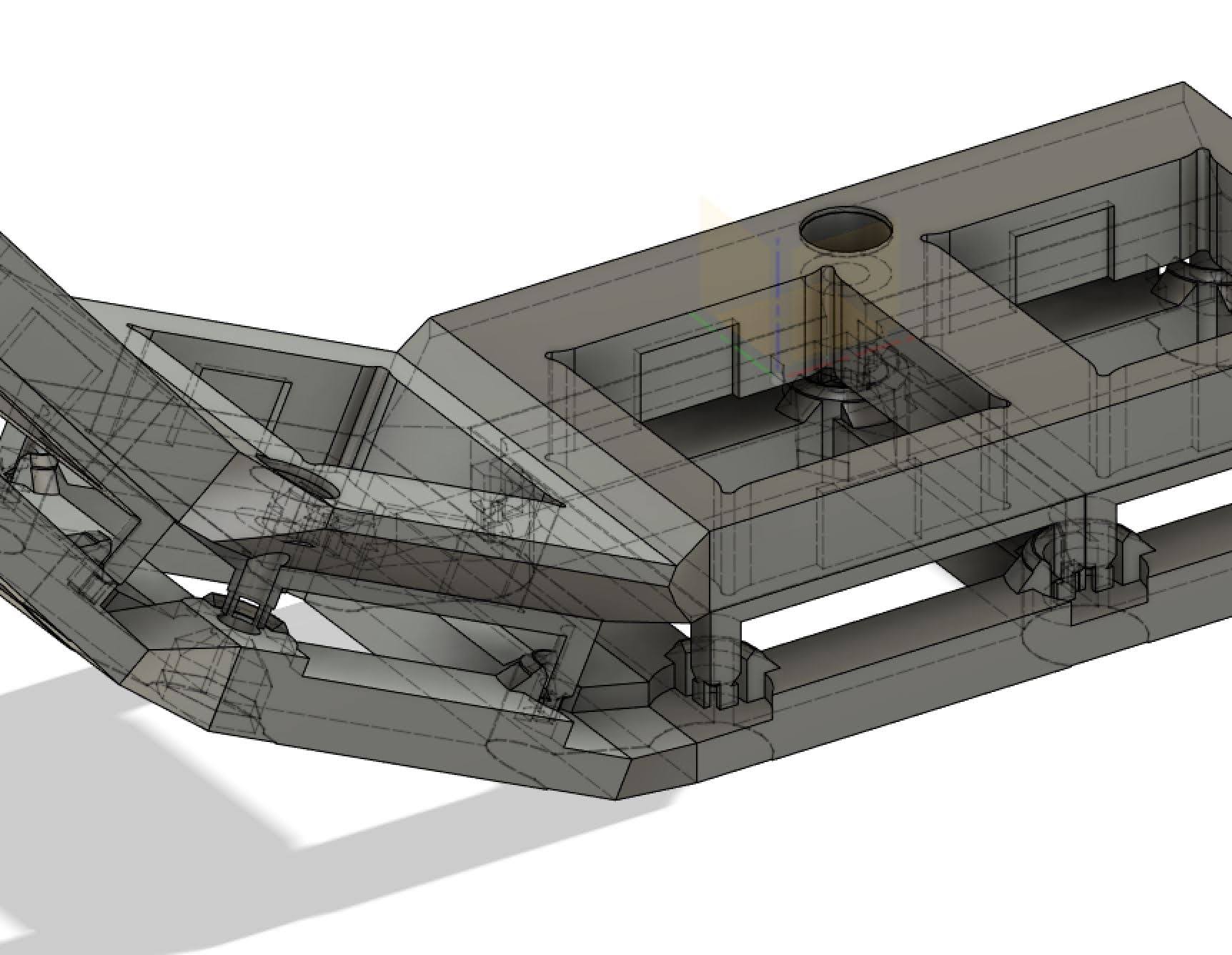
I spent quite some time figuring out the design for the individual key holders. I’ll probably write a separate post just for those. There’s actually two parts. The top is thick, simple and does the job of actually holding the key. The PCBs sit just underneath. There’s space for the wiring between them. The tricky bit is the only space between the PCBs is at their corners. I designed some posts that:
- Are only loosely connected at the tip so the whole holder can be printed in one go and snapped apart
- Hold the PCBs in place with a friction fit while I solder them — the primary purpose
- Align the bottom of the key holders
- Keep the top in rigid contact with the bottom and transfers force — the PCBs are actually floating
- Are replaced by a few screws in key locations to stop the top falling off
After trying them out I’m pretty happy with the result. That said, there probably isn’t any other way to work with the PCBs. After printing both sides a few posts did break at the wrong place, but they were easy enough to glue back.
Shape
Again, I’m making a MS Natural 4K replacement, so I need to hammer down the shape of the keys.
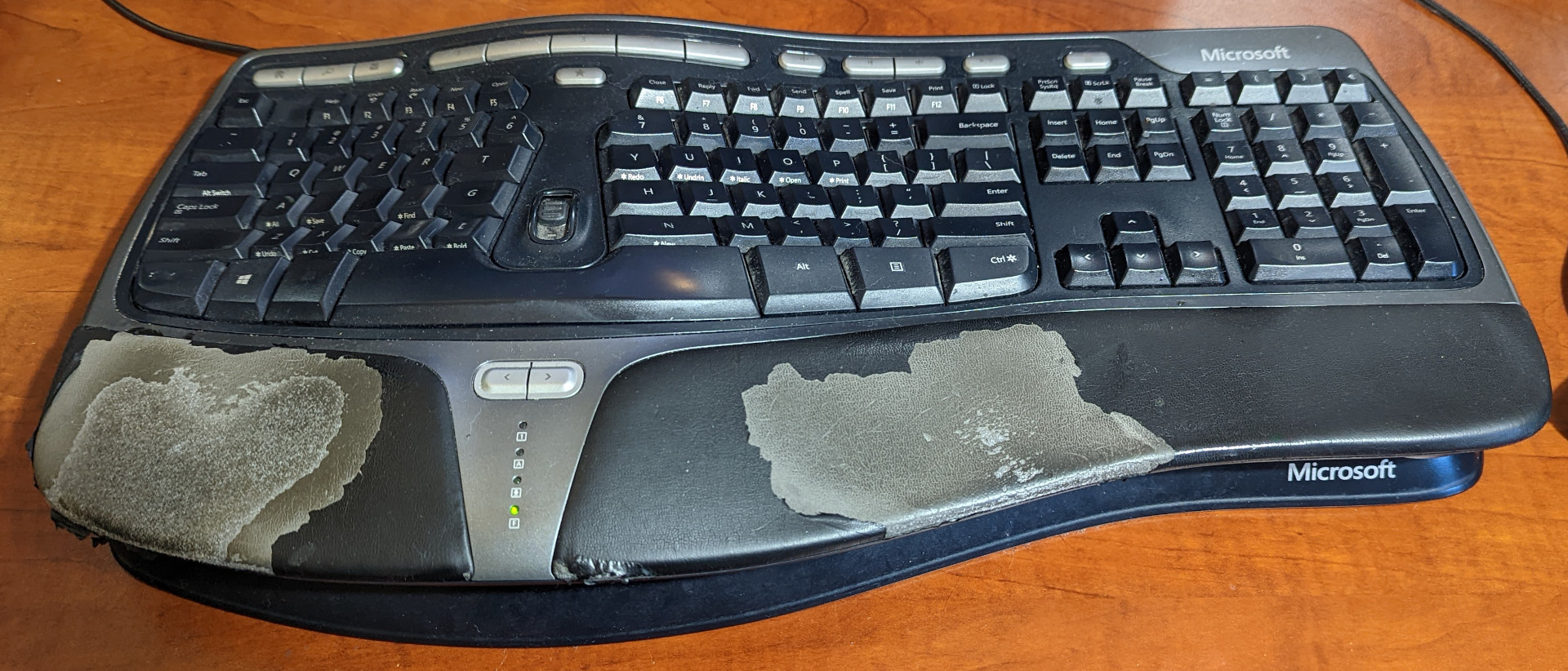
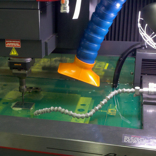
Naturally I took my years of keyboard design and human physiology experience and… lol, I don’t have any of that. So I found this photogrammetry software, Meshroom. Just with my phone I took some photos of my old natural 4k and used Meshroom to create a 3D model of it. The ease of use of this software out of the box is just incredible. Drag in the images, click go and wait. It’s even textured so you can see where I’ve worn through the palmrests. Actually this was quite helpful later.
Getting this into Fusion360 was a story in itself. See Matching complex shapes for a custom keyboard in Fusion360.
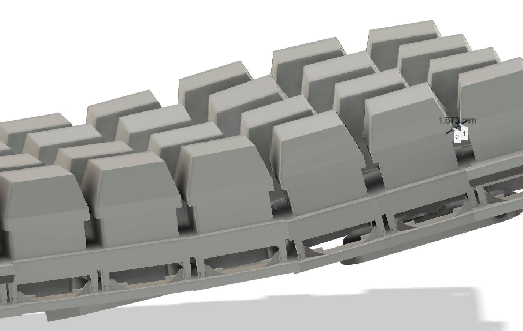
Finally I had the main board layout designed. I did manually tweak the orientation of the key holders, smoothing the transitions between each one. It was quite important to create some fake switch and keycap geometry to verify they had clearance.
Joining the individual key holders wasn’t so straight forward. I tried two ways:
- I made each holder over-sized and then boolean unioned them together. Some geometry did interfere, so I went back in the timeline to before the union and subtraced extrusions from the top faces of each key holder from the neighboring keys. The mesh geometry looked a little messy but it wasn’t really a problem after printing.
- For the right half I tried under-sizing the key holders and lofting them together. Don’t do this. Fusion360 can’t take it and would freeze for 10s of seconds if you sneezed or looked at it funny. Lofts also fail if the start/end doesn’t face each other perfectly and it’s much more fiddly.
(Enough writing for the day. To be continued…)
Adjustability
Not having made a keyboard before or even used many with a thum cluster, I knew I wanted some adjustability. It took me some time to find the right search terms and I spent a long time dreaming about what could be…
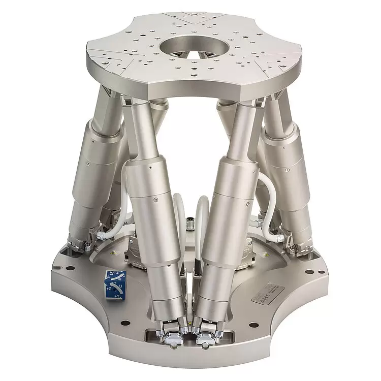
This is a 6-degree-of-freedom “stewart platform”. How cool would it be to place a palmrest on something like that!
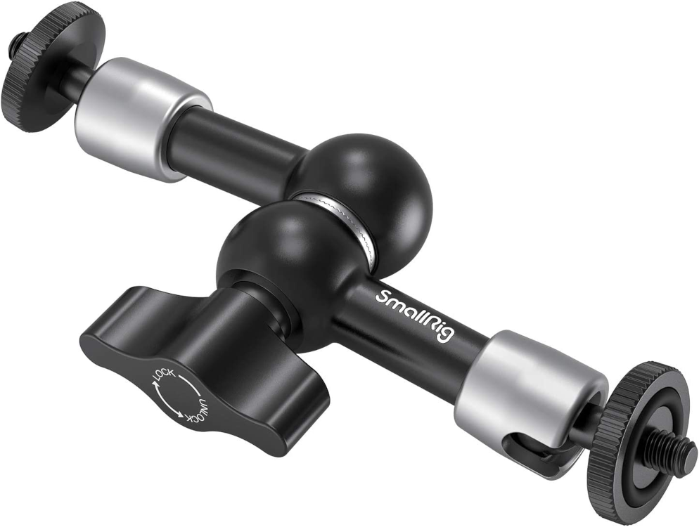
This is a “magic arm”, or aticulating arm. Turn one knob and the whole thing tightends up in one position. It’d be great not to have to fumble with screws with each adjustment.
These are ball and socket arms. Well known examples are Loc-Line and Joby GorillaPod. They’re friction based, but if they can hold a 2kg camera they should be able to hold a thumb cluster.
Sadly, I made the call that integrating these ideas would be complex to even try. It’d need a lot more space to fit the mechanisms, it’d add significant design time and would be yet one more thing that could go wrong, e.g. if it wasn’t strong enough.
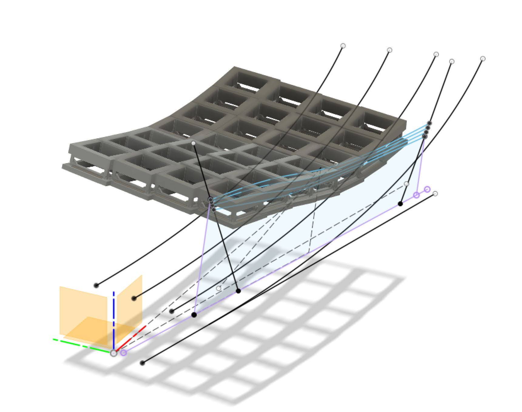
Then an idea hit me. A strength of 3D printing is quick prototype iteration. What if “adjustability” was more just re-printing the keyboard? This would not work for the little 1x1 PCBs because the keyboard is not flat and after soldering the connections between them they are held in place by the plastic nubs between them. However, a middleground would be to be able to print separate adjustment blocks. E.g. spacers or mounting arms with different shapes.
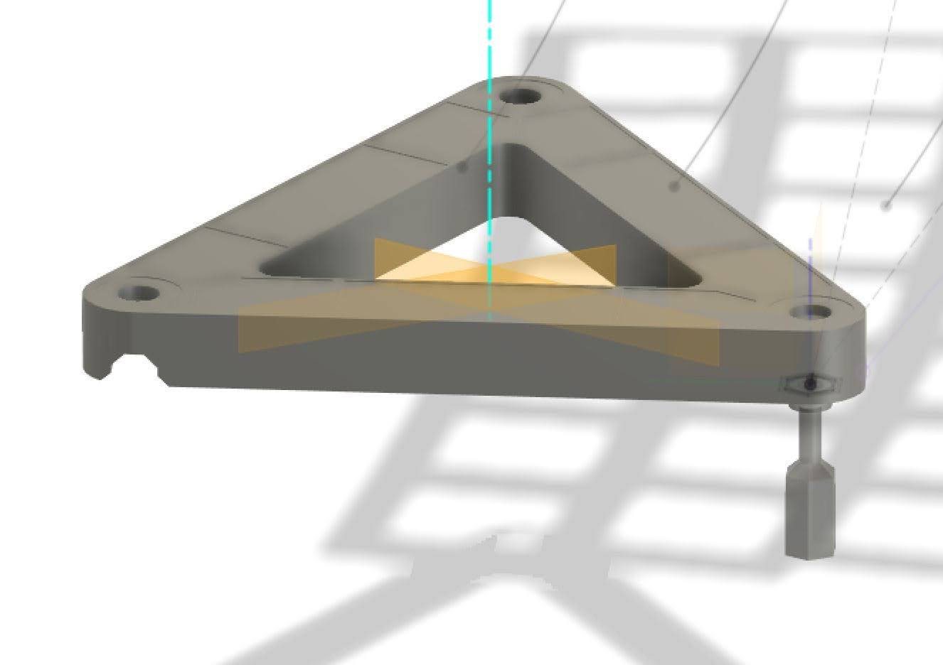
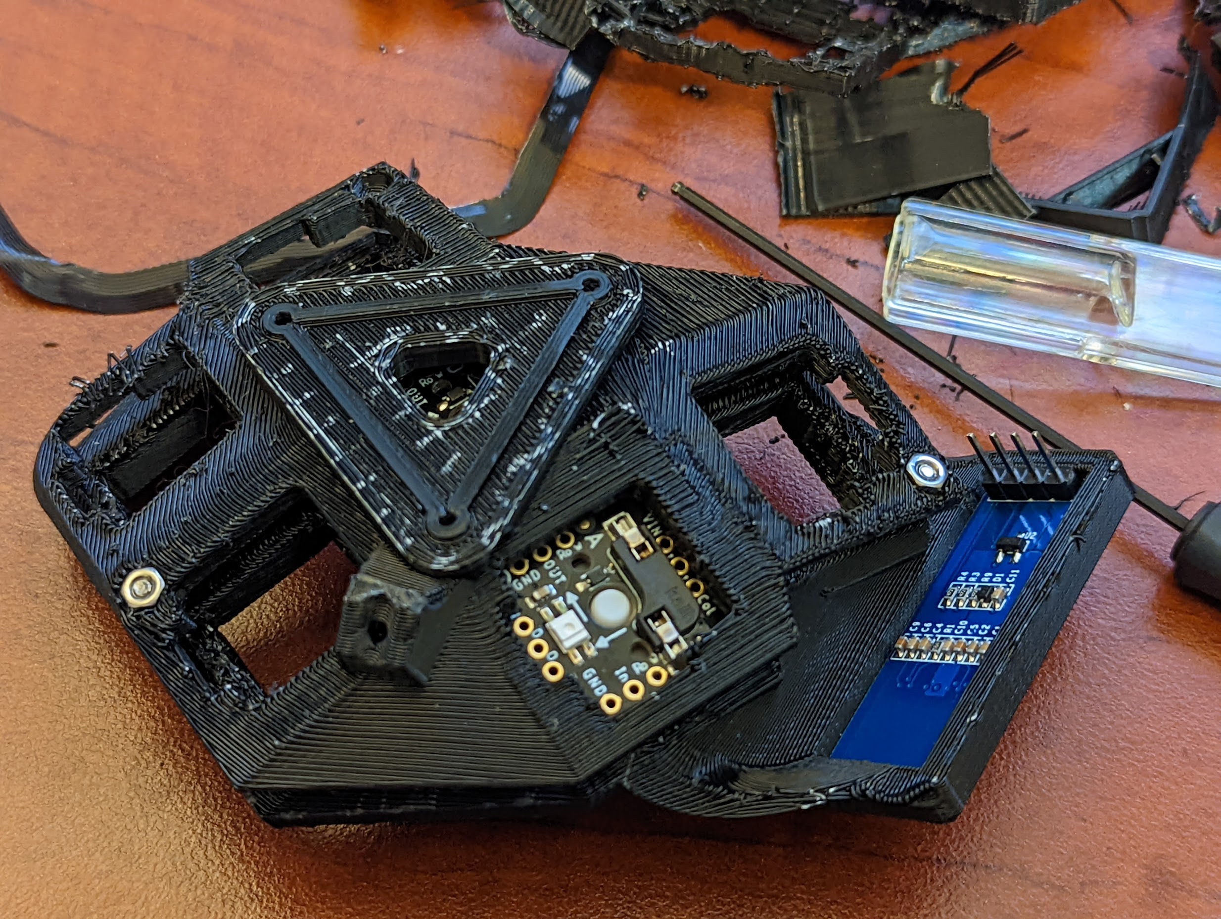
I designed an interface that I could copy and paste to connect larger components to each other. Two for the main keyboard, one for the thumb cluster and one for the palm rest. I had custom cables with connectors to easily disconnect the thumb cluster from the microcontroller on the main board.
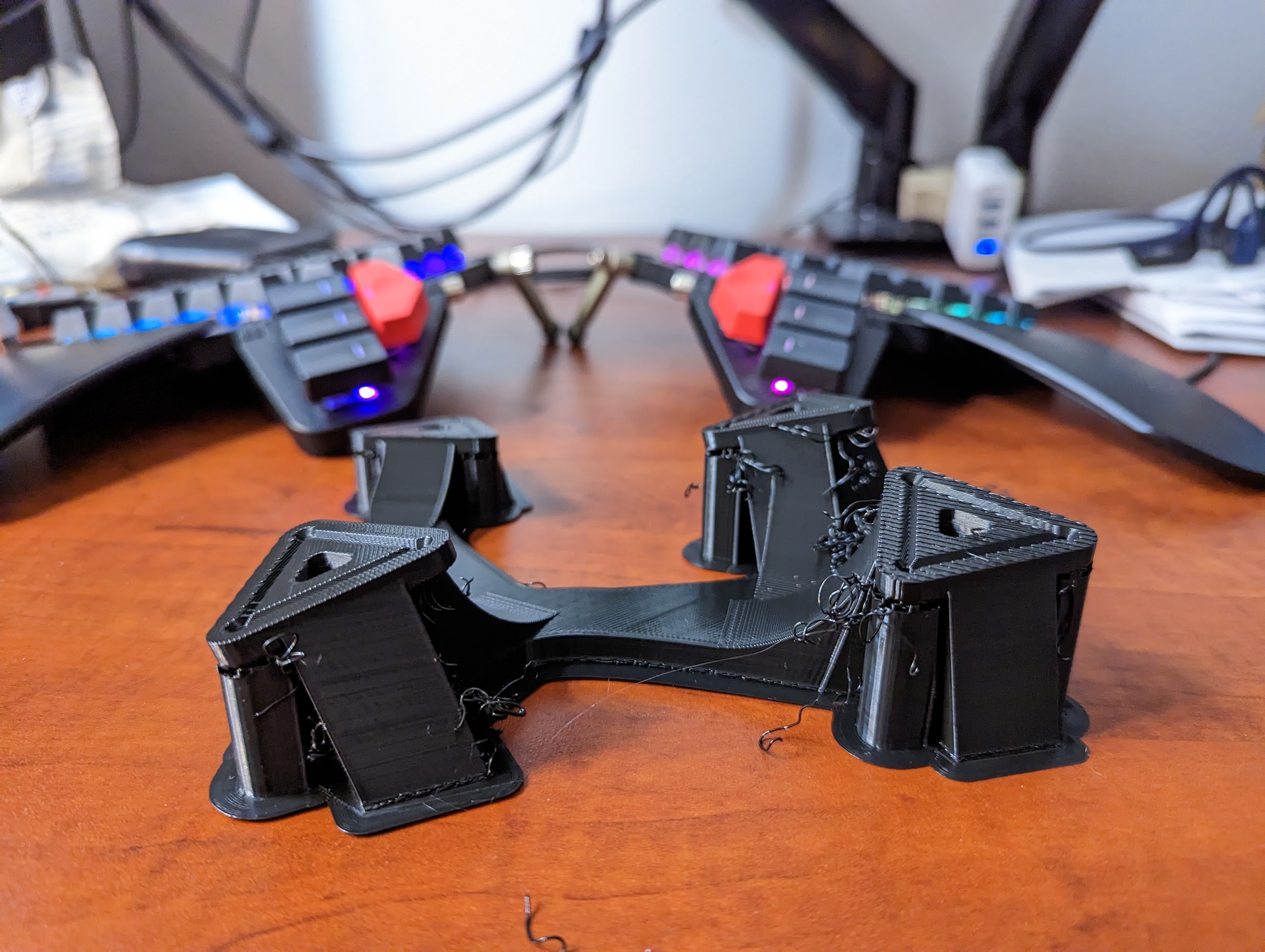
Now in the event that the thumb cluster or palm rest was in the wrong place I could re-print a new frame with the parts in better positions. The images above actually show exactly that. Sometimes you just have to try it first. Soon I imagine we’ll be able to project our hands into a VR environment and try things first.
I had planned to have further smaller blocks for connections between each part and a bigger base frame, but never got around to it. Keeping in mind how a screwdriver can access fasteners during assembly is important.
Thumb Cluster
At first I wasn’t sure if I wanted one. Now I’m totally sold on the thumb cluster idea. It took a bit to get used to but it was well worth the time investment. Thumbs are so strong and versatile they can be doing way more work than just hitting space. In fact the main reason I went to ergonomic and then split keyboards was from pain in the 5th finger from holding down Ctrl in an awkward position all the time. The MS Natural 4K and ergonomic boards were great for me because they reduced this strain, but a thumb cluster avoids it completely.
Where should the thumb cluster be? The space bar on standard keyboards is good evidence of what can be comfortable to press. Many split keyboards such as ErgoDox have thumb keys on the the same flat PCB and plate, probably for design and manufacturing convenience. In this case the thumb presses the keys vertically down, like playing a piano. In contrast, Dactyl-ManuForm based boards have quite an angle, making the thumb move with more of a gripping motion. My guess is these boards, like the Moonlander, are quite sensitive to hand size.
Two rows of keys in a thumb cluster is great for being able to hold multiple keys down at once. In this case positioning them becomes more important because all keys still need to be able to be pressed individually. This can be helped by raising or tilting the back row forwards. The keys can also be a little closer to the hand, in which case the closer row is activated by curling and using the tip of the thumb.
I can stretch a tenth on a piano so I thought larger distances would be OK. That said, this was a big unknown to me so I decided to make it adjustable, as discussed above. The first thumb cluster design worked great in my head, but the position was too far away from the board, forcing the hand open up too much. Adjusting it didn’t help — it was big and bulky because it was a separate part and simply could not fit where I needed it to.
Looking back, my thumbs rest pretty close to the B and N keys so keeping the thumb near there should have been the goal. I learned from this the second time around when making the right half. I’d put the keys even closer if I could.
After living with the moonlander for a few months I have also found that 4 keys per thumb was a decent number. Maybe one day I’ll try to get back to 6.
If anyone’s interested, the layout I currently have is:
- Left: Ctrl, Shift, Alt, Layer1 (Holding Ctrl+Shift is easy; Tab is next to G, so Alt+Tab and Ctrl+Tab are easy)
- Right: Super, Shift, Space, Layer1 (Holding Layer1+Shift is possible but I mostly use the left)
- Layer1 gives me arrow keys under [I, J, K, L], Enter next to N and some more symbols on the left.
My only complaint is space is needed on the left for gaming, so I have a separate gaming layer that I toggle.
Assembly
TODO
Software
TODO
Hi! Is it possible to get some models so I can also make it?
– anonymous, Sep 13 '23Hey. Thanks for your interest! I’ve uploaded the files here, but fair warning it needs some work. The left half really needs to be redesigned to be like the right with an integral thumb cluster. The distance is not quite comfortable. Models on Thingiverse, QMK fork.
– pknowles, Sep 15 '23hello
– anonymous, Nov 26 '24Hi heuristic42.com Owner.
– anonymous, Nov 10 '25