Prime mover is a fun puzzle game. It’s about designing circuit boards, or rather more about logic circuits. I’m a programmer and have no electrical enginnering training, so this was especially fun reinventing a few wheels. The final problem is to implement a very simple processor. This post broadly describes how I solved it. The problem is a significant jump in complexity and took me ~50 hours. Spoilers ahead!
The game
Game mechanics compared to real circuits:
- Rather than binary signals, numbers move along wires.

- There is only one sensor and it can only tell whether a number is positive, negative or zero.

- Board space is very limited. There is a way to nest circuits, but they only have 4 wires for input/output.

Processor - problem description
As always it’s very, very important to understand the problem first before trying to solve it. Of course I knew this beforehand. But don’t think that stopped me wasting a bunch of time making the mistake anyway :)
There are three input wires and one output wire. Input A contains the instructions. B and C contain constant data for the instructions:
- Move B to pos C - Take the number from input B and store it in the register index given by input C. E.g. if B is 5 and C is 2, store 5 in the second register.
- Copy *B to pos C - Take the value in the register at index given by B and store it in the register at index given by C. E.g. if B is 1 and C is 2, copy the value from the first register to the second.
- Add B to C - Add the values in registers at index given by B and C, then store the result in C.
- Sub B to C - Subtract the value in register B from C and store the result in C.
- Send *B to D, C times - This is the output instruction. C is 2 in the last two problems.
- If *B is greater than 0, jump to relative instruction C in program - Only jump if the value in register at index B is positive. The jump can be positive or negative. E.g. If C is -1, repeat the last instruction. If -2, go back to the second last instruction and continue from there. If C is 1, skip the next instruction. This is a real challenge to implement.
A final instruction 0 will end the program and must reset the entire processor. That is, destroy all values in registers and any instruction memory.
My big mistake was thinking the data was separate to the instructions, i.e. a jump instruction could rewind or skip some values in input A but B and C would have new data for those instructions. This is not the case. Values in A, B and C make groups of three and a jump affects all of them. Note that the last instruction 0 is an exception and does not contian B and C data.
One last note. The processor only has 100,000 ticks to complete all programs! Seems like a lot compared to previous problems, but I overshot by ~10% before optimizing.
Possible shortcuts
Based on the current input (Dec, 2020) the following can be useful shortcuts to take:
- You only need 4 registers
- The maximum jump is -5, so you only ever need to store 6 instructions. In fact the only values -5, -3, 2 and 3 are used.
- There is never a negative jump that goes back further than a previous negative jump.
- You don’t need to handle subtracting negative numbers.
Design
The processor starts with the inputs - numbers on A, B and C. It needs a way to perform different instructions based on the value of A. Some instructions require loading register values and sending them to other components. Some instructions produce new values which must feed back into registers. Only the output instruction needs to be sent to D. Finally, the jump instruction feeds back to affect the input instructions. There also needs to be some synchronization, so we don’t start processing the next instruction before the last one finished etc.
Clearly there’s going to be some components and the instructions will dictate how data is transferred between them. I assume there are many ways to implement all of this, varying in how hard coded components are. Perhaps each A+B+C instruction could move on a big wire loop through all the components and each component would be able to read it when appropriate and know which step of the instruction. That sounds absurdly complicated so I decided to break up instructions and generate smaller and more primitive commands based on each instruction. This means that each instruction on A is more like a higher level assembly-like command and I would be generating machine code dynamically. Figuring out the right set of internal instructions, including necessary synchronization, was tricky but perhaps the most creative and rewarding part.
To handle the jump instruction I would have a component on the A/B/C inputs that could be sent either a value to send the next instruction, or a value to jump forwards or backwards. The implementation of the latter I left for later. This was fed by a simple component that could also do an inline compare.
To connect all the components together I chose to have a bus where I would first send an address number, followed by one data number. To send multiple bits of data I would need to re-send addresses, but this could be pipelined (send 4 numbers without waiting for any to finish). The image below shows the overall component layout and addresses. Note that the register and add/subtract outputs feed back into the synchonization compoennt. A special zero address is used to wait for and load values onto the bus as either an address or data.
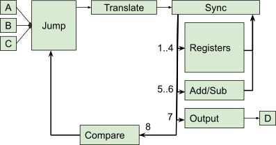
It’s not a coincidence that this matches the board in the solution too:

Components
Address router
These were modules placed along the main bus. They would decrement the first number, the address, and if it were zero route subsequent data value to the component. Otherwise it would let the next data value pass through unaltered.
I actually had another varient inside the instruction translation component, which routed instructions and their B/C constants to separate blocks that would do the translation for each. The difference was these operated in threes, routing two following numbers depending on the first.
Translate
This took most of my time but was probably the simplest. A/B/C instruction triplets were routed to hardwired circuits to generate various sub-instructions in the right order. Here’s what it would need to send for each instruction. Most sub-instructions would be in pairs of (address, data) with the exception of 0 which would send the following value as an addres, then wait for and then load a data value from registers/add/subtract. Originally this could also load the value as an address, but there are no instructions that require this (after I realised B/C data is attached to A).
1 - Move B to pos C
- C (register address)
- 1 (register store)
- C
- B (data)
- 8 (jump address)
- 1 (load next instruction)
2 - Copy *B to pos C
- B (register address)
- 2 (register load)
- C (register address)
- 1 (register store)
- 0 (data input after address, send B as data to C)
- C
- 8 (jump address)
- 1 (load next instruction)
3 - Add B to C
- C (register address)
- 2 (register load)
- B (register address)
- 2 (register load)
- 0 (data input after address, send *C to add)
- 5 (add address)
- 0 (data input after address, send *B to add) -> outputs result
- 5 (add address)
- C (register address)
- 1 (register store)
- 8 (jump address)
- 1 (load next instruction) — do this early to save time
- 0 (data input after address, send result to *C)
- C
4 - Sub B to C
Same as Add, but with 6 for sub address. Both add and subtract took advantage of this and used the same generation circuit.
5 - Send *B to D, C times
- B (register address)
- 2 (register load)
- 7 (output address)
- C (number of times to duplicate)
- 0 (data input after address, send *B to output)
- 7
- 8 (jump address)
- 1 (load next instruction)
If *B is greater than 0, jump to relative instruction C in program
- B (register address)
- 2 (register load)
- 8 (jump address)
- 2 (to offset if greater than zero)
- 0 (data input after address, send condition *B)
- 8
- 8
- C (jump to this instruction)
- 8
- 1 (load next instruction)
End program (instruction 0)
This instruction clears the internal memory of the processor.
- 1 (register 1)
- 1 (clear)
- 2 (register 2)
- 1 (clear)
- 3 (register 3)
- 1 (clear)
- 4 (register 4)
- 1 (clear)
- 8 (jump address)
- 2 (to offset if greater than zero)
- 8
- 1 (greater than zero)
- 8
- 0 (jump to offset zero)
Register
- 1 to clear and be ready to store the next value
- 2 to load the current value (sends it to Sync)
Sync
This component does a few things:
- Adds a little delay between each sub-instruction
- Keeps input from registers/add/subtract behind a gate until sub-instruction 0
- When a zero is encountered it sends the next sub-instruction value as an address and then the data input.
The unexpected ordering of the 0 operation is required because input is needed as data. The address can’t be sent first and then a zero as a special “read from the input” because it would be ambiguous with other real data values of zero.
Compare
- 1 is a passthrough to jump - simply load the next instruction
- 2 is a compare and jump that expects two more values
- The first is the compare value (no-op if it’s zero or below)
- The second is the value that is sent to jump if the first was positive.
Custom synchronization here was added to make sure a 1 would not be passed through if a jump was in progress. Sadly this was timing based and the jump replay took a very long time. Program 4 was a big bottleneck.
Jump
This one isn’t the work I’m most proud of. As I understand, a real processor would fetch instructions from some memory. Rather than keep an instruction counter I opted to feed the instruction translator with a stream. This meant I needed to keep a queue of 6 recent instructions that I could replay if needed.
It also needed to keep groups of 3 (A/B/C). Rather than linearize the inputs I chose to duplicate the entire jump module three times. The same input would be sent to all three jump components.
If this unit received a 1 it would send the next value to the translation component. The next value may be waiting after the replay feedback or on the input before the replay is recorded, which added some complexity.
If the unit received a value greater than 1 it would skip that many values bar one. E.g. a 2 skips 1 value. However the skipped values would still be recorded for subsequent replay if needed. A subsequent 1 value would be sent to the jump unit after any skip happened to then run the following instruction.
If the unit received a negative value it would replay that many instructions. It would actually discard any remaining instructions, but thankfully no program exposed this flaw. This was implemented with one queue along a single wire (the basic idea for the queue is shown in the image below, with the input on the left, release on the top and output on the right). When replaying I needed the n most recent items. Since the queue was FIFO and the most recent input would be at its tail I had to reverse the queue, take only the first n and then reverse the result. My reverse implementation was timing dependent and took aaaages.

Finally, a special value was needed to empty and discard the queue when the program finishes. This almost came for free as “replay zero values” gives the same result. Because allowing positives, negatives and zero through logis is fiddly in prime mover I subtracted 1 from all replay values until they made their way into the inner-most circuits.
Programs
For my own reference, it was incredibly helpful to copy out the programs to a spreadsheet, where A, B and C could be side by side. I could also write notes about what the expected output was. For debugging and optimizing performance I’d also keep the tick that they were processed at.
As of Dec, 2020…
Program 1
| A | B | C |
|---|---|---|
| 1 | 5 | 1 |
| 1 | 1 | 2 |
| 1 | 0 | 3 |
| 4 | 2 | 1 |
| 3 | 2 | 3 |
| 5 | 1 | 1 |
| 5 | 3 | 1 |
| 6 | 1 | -4 |
| 0 |
Program 2
| A | B | C |
|---|---|---|
| 1 | 1 | 1 |
| 1 | 1 | 2 |
| 1 | 4 | 3 |
| 1 | 2 | 4 |
| 4 | 4 | 3 |
| 3 | 1 | 2 |
| 5 | 2 | 1 |
| 3 | 2 | 1 |
| 5 | 1 | 1 |
| 6 | 3 | -5 |
| 0 |
Program 3
| A | B | C |
|---|---|---|
| 1 | 5 | 1 |
| 2 | 1 | 2 |
| 2 | 2 | 3 |
| 1 | 1 | 4 |
| 4 | 4 | 1 |
| 5 | 3 | 1 |
| 3 | 2 | 3 |
| 4 | 4 | 1 |
| 5 | 3 | 1 |
| 6 | 1 | -3 |
| 5 | 1 | 1 |
| 5 | 2 | 1 |
| 5 | 3 | 1 |
| 5 | 4 | 1 |
| 0 |
Program 4
| A | B | C |
|---|---|---|
| 1 | 1 | 3 |
| 1 | 0 | 2 |
| 1 | 15 | 1 |
| 3 | 3 | 1 |
| 4 | 3 | 1 |
| 6 | 1 | 3 |
| 5 | 2 | 1 |
| 6 | 3 | 2 |
| 5 | 3 | 1 |
| 6 | 1 | -5 |
| 0 |
Output D: 15 x 1s, 0
Program 5
| A | B | C |
|---|---|---|
| 1 | 1 | 3 |
| 1 | 8 | 2 |
| 4 | 2 | 3 |
| 5 | 3 | 2 |
| 0 |
Program 6
| A | B | C |
|---|---|---|
| 1 | 16 | 1 |
| 5 | 1 | 1 |
| 1 | 3 | 2 |
| 5 | 2 | 1 |
| 1 | 1 | 3 |
| 1 | 0 | 4 |
| 4 | 2 | 1 |
| 3 | 3 | 4 |
| 5 | 4 | 1 |
| 6 | 1 | -3 |
| 4 | 3 | 4 |
| 2 | 4 | 1 |
| 5 | 1 | 2 |
| 0 |
Output D: 16, 3, 1, 2, 3, 4, 5, 6, 5, 5
Looks like markdown tables are broken :(
– anonymous, Dec 28 '20this should be fixed now
– pknowles, May 23 '23