In my last post I talked about a MS Natural 4K replacement. I eventually decided I was going to build one from “scratch”. And here it is in all its glory. I call it “DerBard” and I’m typing this post with it now.
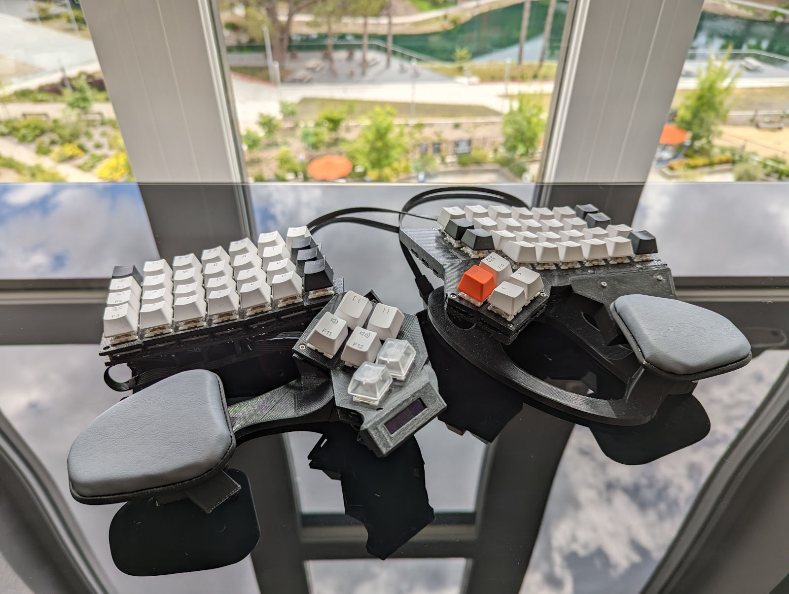
It’s an ergonomic split 65 key keyboard with inbuilt palmrests, backwards tilt and per-key RGB lighting. It’d a dream for typing text. Probably because it was designed to match the raised MS Natural 4K that I already love. The left thumb cluster is plain bad and needs redesigning. The redesign is on the right.
It’s fully programmable with an Arduino ATmega32u4 (Elite-C V4 board), runs QMK, has a 128x32 pixel display, buzzer and animated indicator LEDs that I use to show what layer is active. I’m recycling switches and keycaps from an off-the-shelf board with some clickeys for the modifiers on the thumb clusters.
It took 150 hours to design, 3D print, assemble and program… just the left half. The right half took another 80 hours for a project total of 230 hours. Nearly 6 working weeks but spread out from July 2022 to April 2023. The majority of the time by far was design in Fusion360. The following is the story, mistakes and lots of learning along the way.
Background
This is my quick summary and background before talking keyboard details: Anatomy of a custom keyboard
Mounting the switches
By now I’d been browsing r/MechanicalKeyboards/ for some time and could see I had some options. It seemed like most people were buying PCBs and plates from keeb.io. PCBs didn’t work for me as the whole point of this project was not to make a non-flat MS Natural 4K replacement. Actually there is one caveat here — keycaps come in different heights (e.g. you’ll find function keys at the top are often taller) and a coleague at work showed me you can get a good curve even by gluing on some Lego shims.
I was rather inspired by Dactyl in how a whole board could be 3D printed minus wiring the switches to a microcontroller. I highly recommend the talk. Many people don’t even bother with a flexible PCB and solder diodes and wires directly to the switches. One rather eye-catching project was a Dactyl Manuform with hot-swappable sockets. This is where I thought I’d start.
I recently bought a CR-10 printer and started learning Fusion360. My plan was to design a keyboard just like dactyl in that the shape could be quite organic. The starting point for designing a switch mount was this video by Bastard Keyboards. The reminder to print test pieces along the way is a great tip!
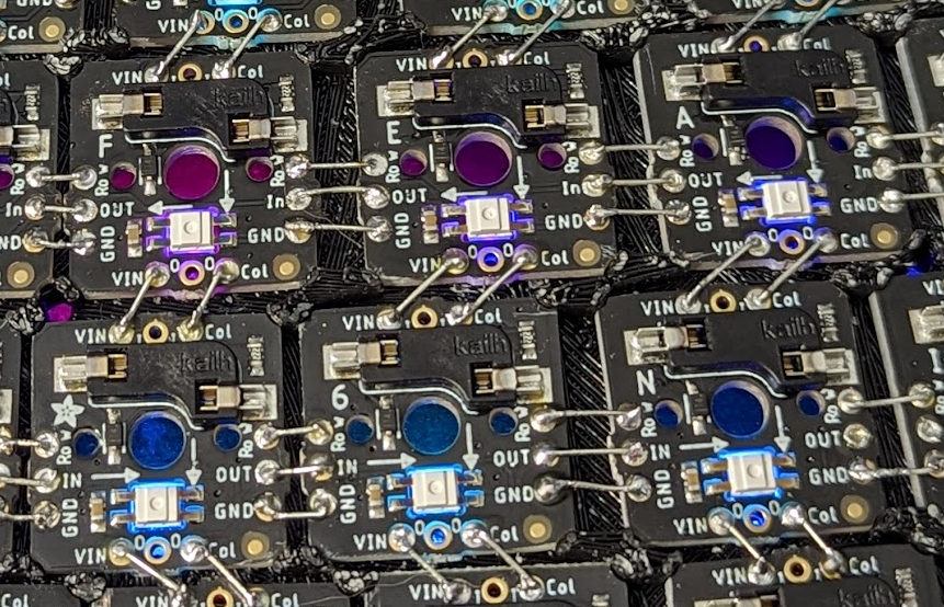
RGB lighting is just a gimmick and doesn’t really make you type faster. I’m kidding, of course my eyes got the better of me. I’ll have some of that! I eventually stumbled upon 1x1 NeoKey PCBs. Pre-assembled socket + diode + RGB LED PCBs with convenient connections to adjacent ones. Not super cheap mind you, but convenient enough for what I’m getting. I found you can buy them in 5x5 snap-apart grids. Three sets for $90 + postage and that’s just the start. Fair warning: you don’t want to run these at full power unless you have a 20% size keyboard.
Shape
Again, I’m making a MS Natural 4K replacement, so I need to hammer down the shape of the keys.
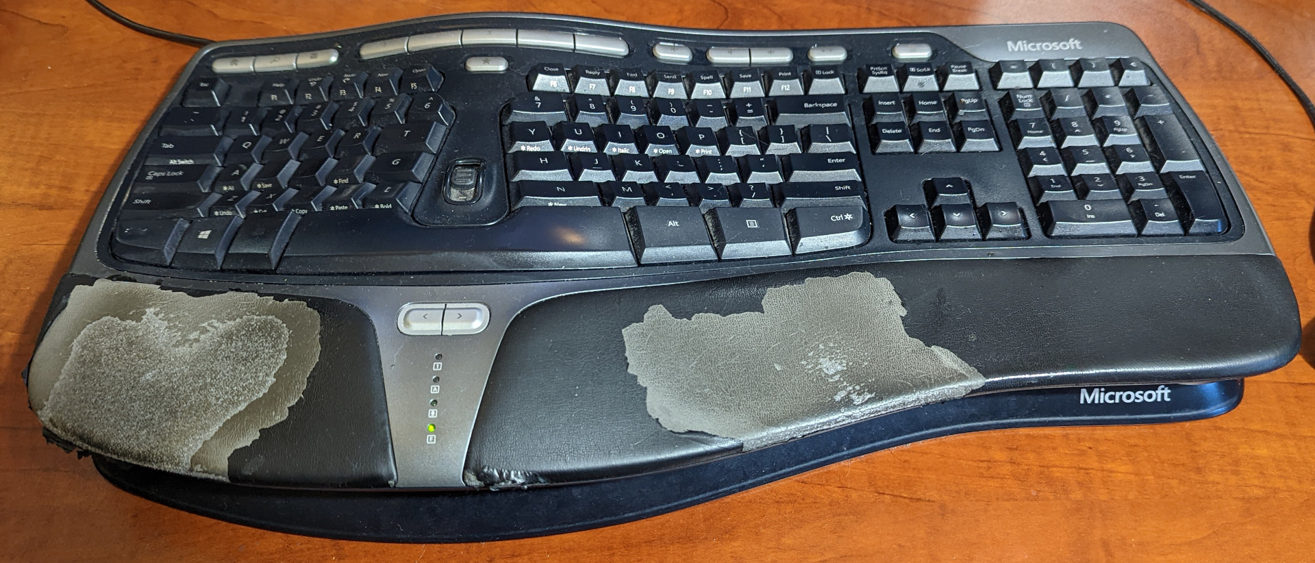
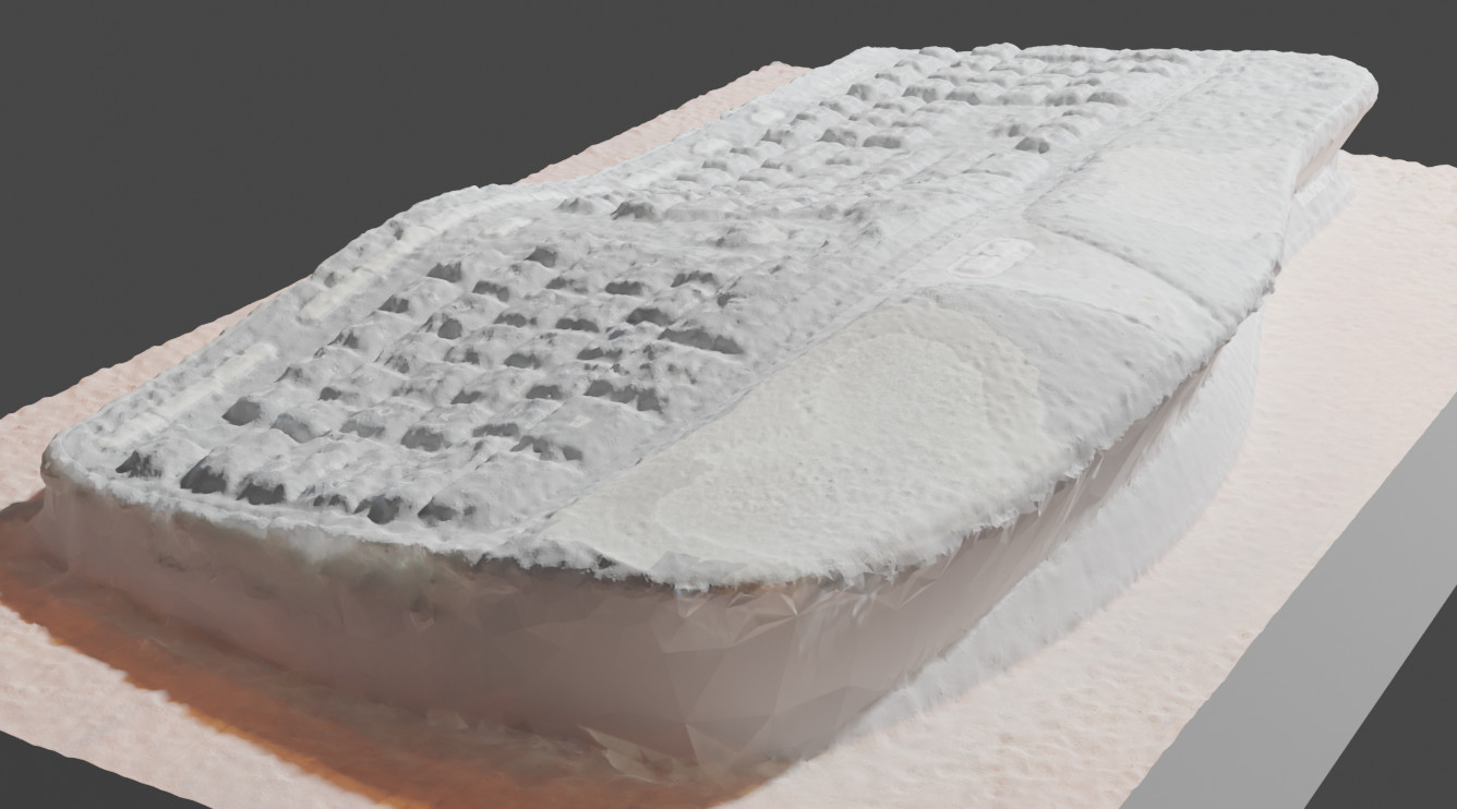
Naturally I took my years of keyboard design and human physiology experience and… lol, I don’t have any of that. So I found this photogrammetry software, Meshroom. I took some photos of my old natural 4k and created a 3D model of it. The ease of use of this software out of the box is just incredible. It’s textured so you can see where I’ve worn through the palmrests. Actually this was quite helpful later.
(Enough writing for the day. To be continued…)