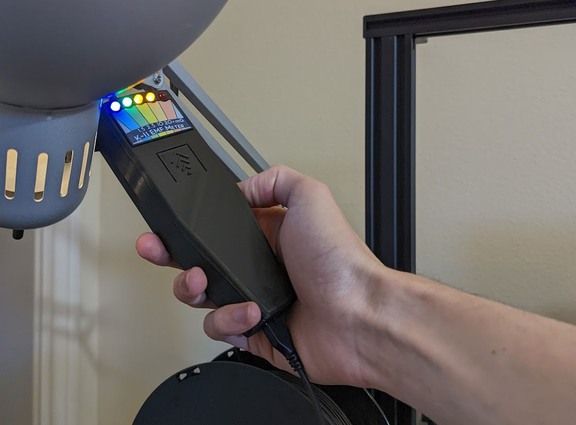
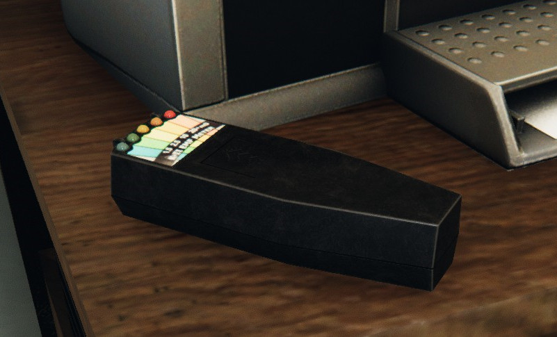
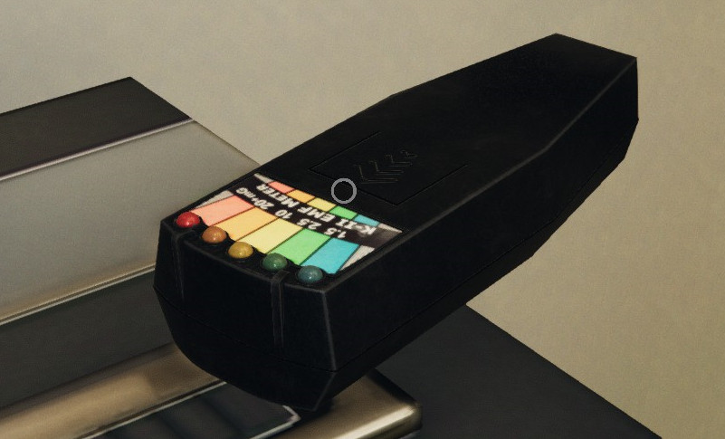
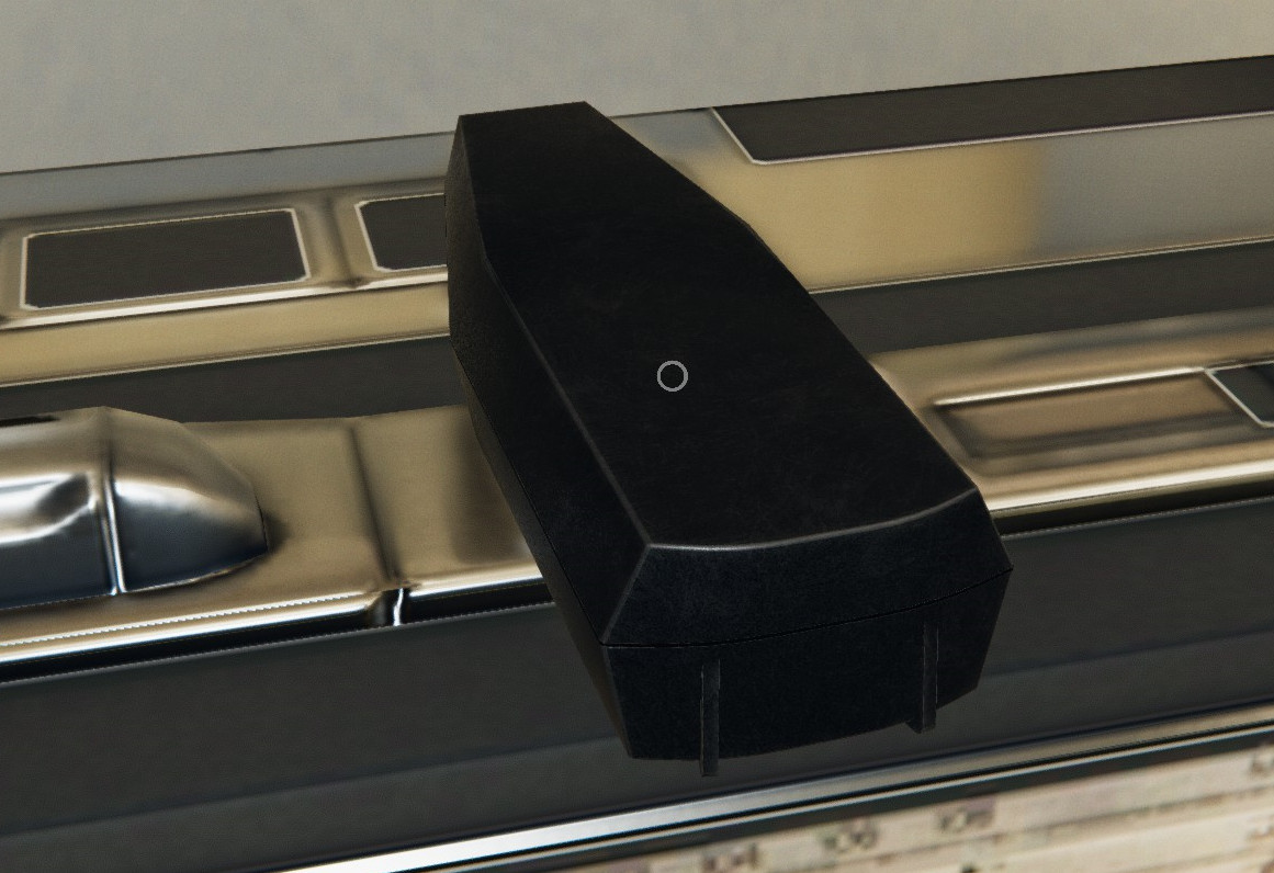
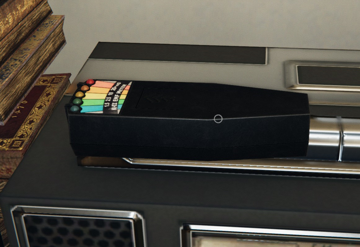
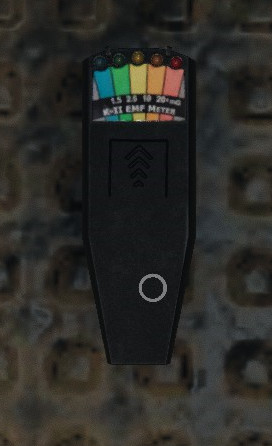
The game phasmophobia by Kinetic Games (on steam) is about finding and identifying a ghost. It is unique in that it’s just about identifying the ghost. There is no combat. Players use various items to help narrow down which ghost it is. One item is an EMF reader that detects ghost activity. With an ameteur electronics background and a new 3D printer I built a real one as a gift. It actually works!
It will “find ghosts” (with clever use of rand()) and actually measure magnetic fields.
Details
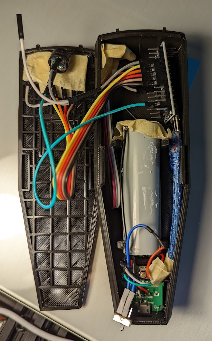
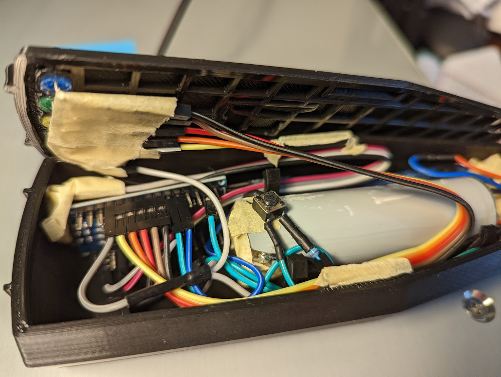
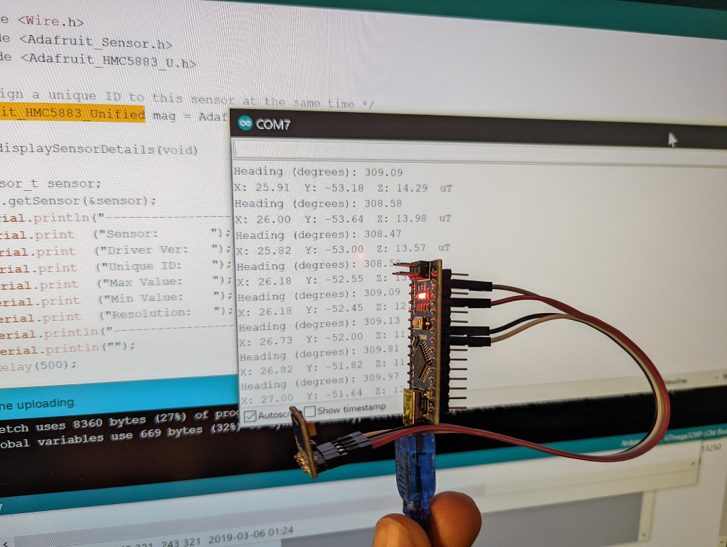
It uses a MEMS magnetometer and an arduino nano to control everything. It’s powered with the insides of an off-the-shelf battery pack. It can…
- Measure direction
- Measure the magnetic field strength
- Generate random “ghost events”, which may occur at a given direction or field strength and then move!
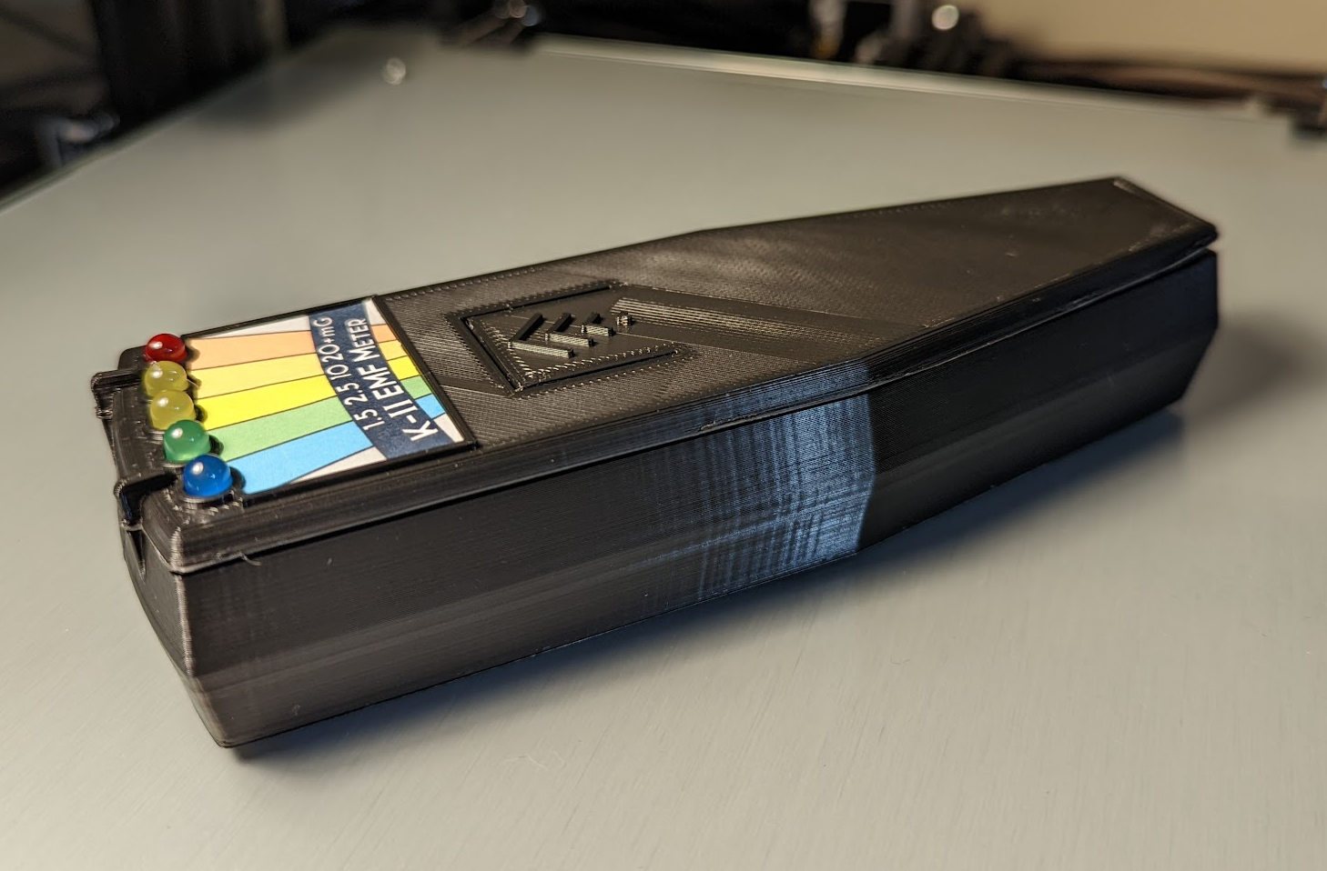
- Play a tone with a buzzer and has 5 LEDs to show the “EMF level”
- Charge via USB - yes, it’s bettery powered
- Be re-programmed by the same USB
- Change modes with the press of a button, e.g. to adjust the “sensitivity” and display debug information
- Display the magnetic field strength (one debug mode) and coarse direction (3 debug modes for each plane)
Pictures
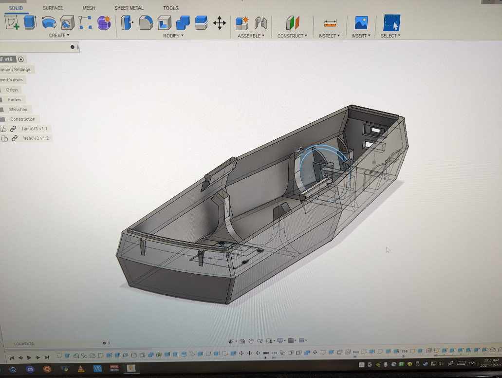
Building
The 3D model was built in fusion360. You can download it on thingiverse. It’s based on a few reference screenshots taken at 4k. I’ve included them at the bottom of the page. Scale was actually loosely based on an arduino uno before I changed plans to use a nano. Point being it’s likely inaccurate but still sits comfortably in the hand. It’s designed to print without support and clip together with friction.
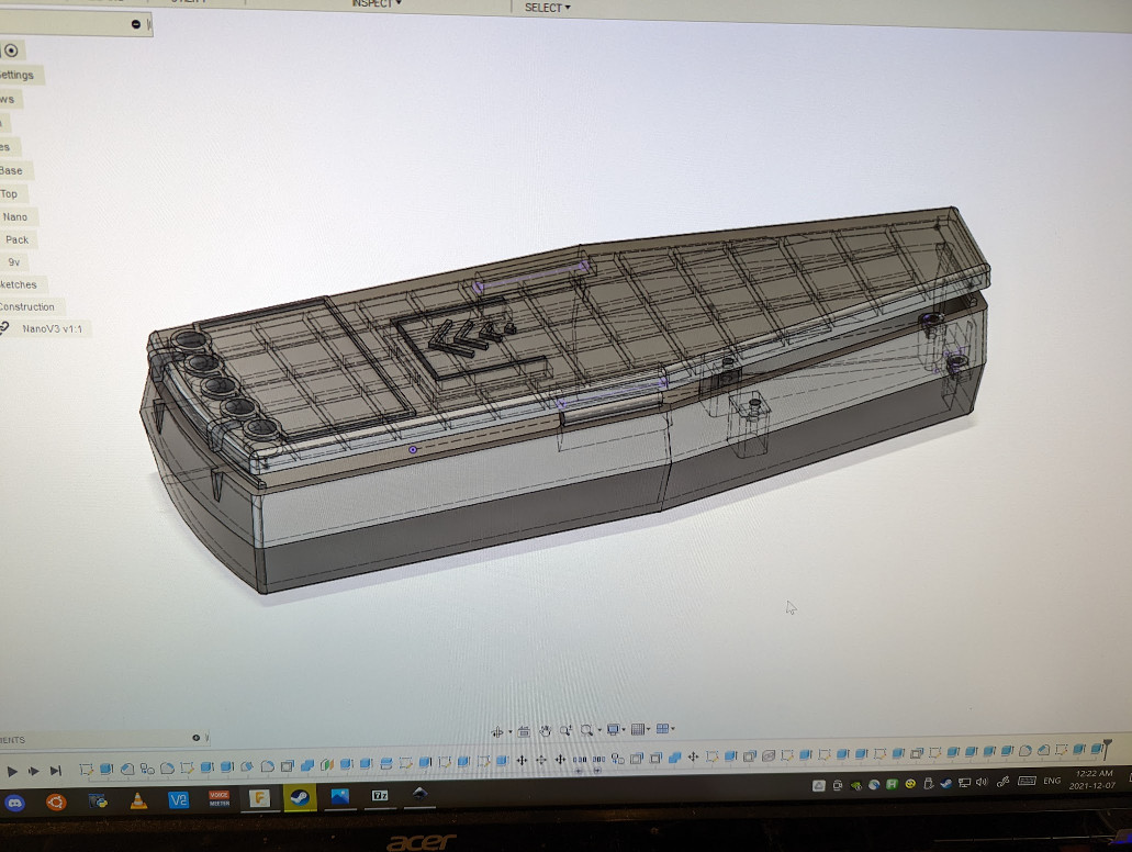
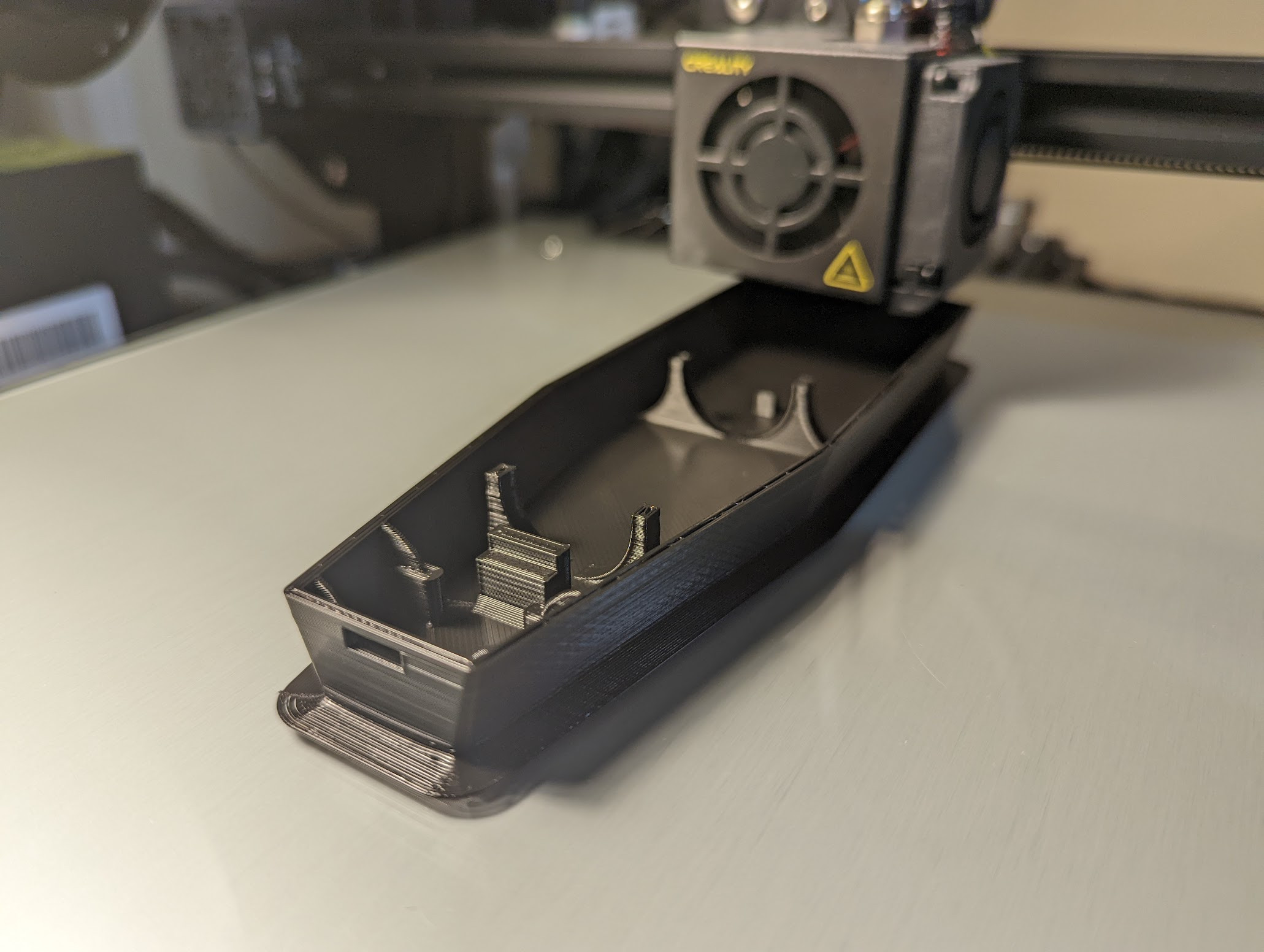
The print went surprisingly well, with the exception of the part shrinking and lifting up off the bed. This is the first large print I’ve done and it was a new experience. It wasn’t such a problem on the base, but there’s a giant gap between the the two parts at the back when they’re connected. I gather a hotter bed temperature might help, but I should also give more base surface area to the model for better adhesion.
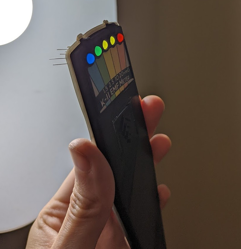
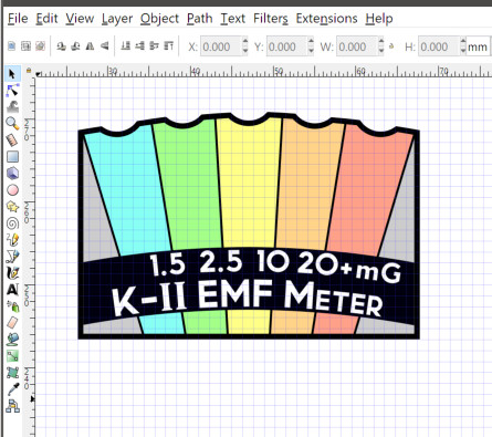
The label was created by hand too. I exported a fusion360 sketch to inkscape, then adding the colored bars and text with a mixture of fonts. I printed it with a regular inkjet and covered it with clear tape before cutting it out with a hobby blade. The SVG is included in the model download.
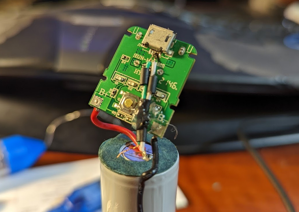
The most physically challenging part was probably soldering the data lines from the battery pack’s micro USB plug to the arduino nano’s USB cable. That this worked was one of my favorite parts of this build. There’s a surprising lack of information out there about getting a rechargable power pack that works with arduino projects. I’d highly recommend this approach, but I wish off the shelf kits with a separate battery and power module/charging controller existed. The battery pack was just a cheap one I found on amazon.
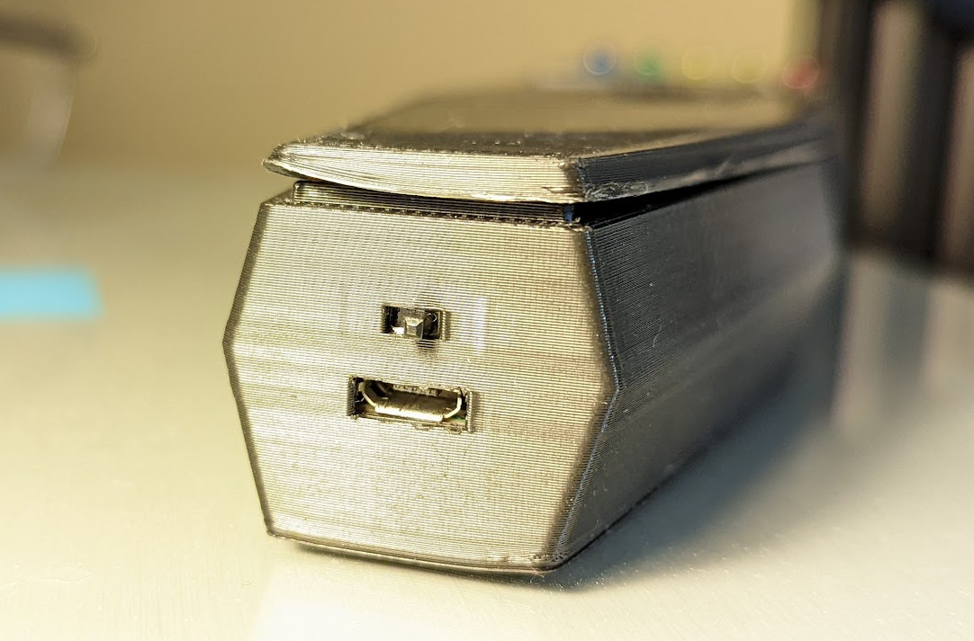
The functional button for changing modes was actually an afterthought. I had modelled the button to match the game and be pressable, but hadn’t had time to think about hooking it up to a real momentary button. By chance, the battery added the perfect height to be able to sit a push button between it and the top of the device. OK, I had to file down the plastic bit of the momentary button ~1mm but then it worked perfectly.
Matching the notches in the battery pack’s charging board to the 3D model didn’t go so well and I needed to scrape away a lot of plastic before it would sit correctly. I also ended up drilling a hole for an M2 bolt to hold the board down as friction was not enough. If I printed it again this would need reworking!
I almost superglued the power switch slider and luckily forcing it one way and the other unstuck it before it dried.
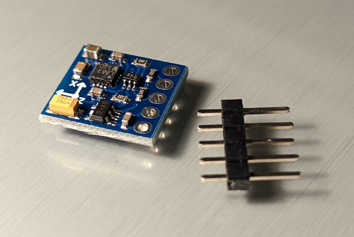
Magnetometer
There are a few devices that measure magnetic fields. Initially I bought a Hall effect sensor. This was not what I wanted and not nearly sensitive
The most challenging part of the software was calibrating the magnetometer. It works great out of the box with nothing nearby, but as soon as there’s a giant batter right next to the sensor suddenly all the readings are way off.
I started with the simple approach of an offline calibration step. I tried MotionCal from adafruit.com which gets you to run some precompiled exe from the net (fun times) but that project wasn’t able to parse the samples from the serial connection that I was printing. At least this is my guess after looking at the code.
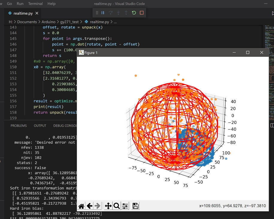
I ended up cobbling together my own calibration in a python script. This reads magnetometer samples — three x,y,z values — from the arduino’s serial output, displays them and re-runs calibration in realtime to see what’s happening. It also caches them to disk so that sampling can be done just once while reworking the calibration algorithm. Code is available on github.
At first I tried some random sphere fitting algorithms I found online, but they were not giving satisfying results at all. Perhaps this was because they were trying to maintain direction accuracy. An accurate direction was much less important for me in this project as I mainly wanted the magnetic field strength. To this end, I used least squares to take the output of the above algorithms and arbitrarily tweak all 12 calibration values to better fit the samples to a sphere. This was done with scipy’s “optimize” library, where the 12 values were a standard 3x3 matrix and x,y,z offset. The result is shown below:
I would have loved to make the calibration keep happening dynamically over time. This is pretty simple to do but without some useful libraries such as Eigen I couldn’t be bothered. There is an Eigen for Arduino (including one that is meant to fit in the limited program space of a Nano) but it’s pretty involved to set up especially when it needs some STL.
Software
There’s not much going on in the software really. In the default state the EMF reader sits in a delay() loop, waking up randomly to trigger a ghost event. An event is either a target direction or magnitude (or a constant always-on state just for fun). The target value interpolates between two values over time to make the “ghost” appear to move. The thresholds are chosen to be near the current values to increase the chance of detection, but also require you to be moving the device around in order to “find” the ghost event. When the current measurement gets close enough to the value, it displays a reading and generates a tone. The EMF level is based on the current magnitude, but may as well just be random.
Surprisingly, many electronics and wiring in walls alters the magnetic field enough for the magnitude events to be meaningful. I.e. moving the device near a wall will actually trigger a reading. In other cases, the direction reading works OK too, but it’s pretty clear that it’s a direction and not near some physical object in the house.
For the tone, I think the frequency from the game is ~650-700hz and it wobbles a bit during a hunt.
Reference images
Wow, It is that famous Ghost buster, isn’t it?. Very unique, based on a scientific model. But you have to test the functionability at a suitable location. Nice example of turning hobby into a scientific project.
– anonymous, Jan 4 '22Sorry for the random quoted text comments. I am one of those people that likes to highlight what they are reading, and your website kept popping up a little box that would not go away… so during my NERDRAGE I guess I was posting comments…
– anonymous, Sep 6 '24ANYWAY! THANKS FOR THIS! I hope you enjoyed your time creating this, IT WAS well spent for our benefit! We truly appreciate you sharing your creation so that we can build this too… but with out the hard work of design,and programming! (well hopefully not much we will see how the project goes!) Thanks again fellow maker!
а есть подробные схемы что к чему подключать и куда припаиваться
– anonymous, Jan 9 '25I don’t have a circuit diagram sorry. The LEDs are all on separate GPIO pins (they need a resistor each). The button circuit is straight from the arduino docs. The buzzer (active) needs a resistor adjusted for volume and a PWM pin. The magnetometer is I2C, controlled by a library.
– pknowles, Jan 13 '25All good/my bad. A half implemented feature that I really should disable. It was definitely a fun project. Thanks for the interest :)
– pknowles, Jan 13 '25Can you show us what the wires go to please.
– anonymous, Dec 16 '25